
Servo Motor Torque Calculation
Convert watts and RPM to torque, then review a 10 mm D-shaft servo motor for high torque using documented interface limits.
Published · Reviewed by Frameless Servo.
Calculate torque
Example: 400 W at 3,000 RPM.
Your result appears here.
Get rated-point torque first. Add documented ratings to compare an interface; a 10 mm D-shaft alone has no universal torque limit.
Find the ratings you needFour decisions before selecting a motor
Calculate a matching operating point
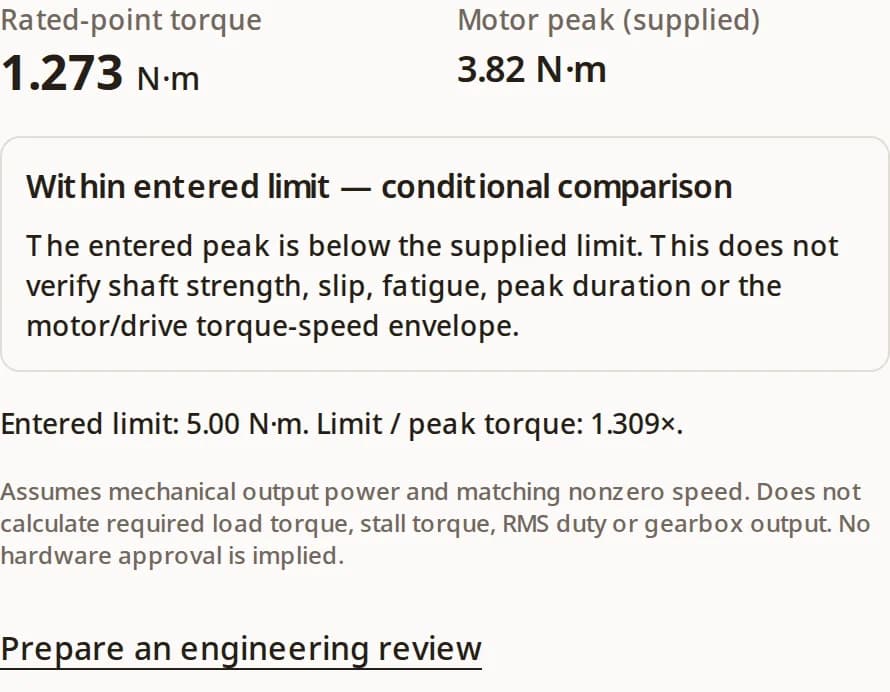
400 W of mechanical output at 3,000 RPM gives 1.273 N·m. Lowering the speed entry while keeping power fixed describes a different operating point, not guaranteed extra torque from the same motor.
Formula and assumptionsPeak is a separate specification
The NX 400 W example publishes 3.82 N·m instantaneous torque. Obtain the selected motor/drive curve and permitted pulse duration; leave peak unknown until confirmed.
NX manufacturer evidence10 mm describes fit, not capacity
A D-flat does not establish the joint’s allowable torque. Shaft material, flat depth, hub, screw, installation and duty must be matched to documented ratings.
NBK test contextCompare the complete joint
Use a limit approved for the actual shaft/hub assembly after application derating. Screw seating torque and coupling slip torque are different quantities.
NBK selection evidenceMethod: watts and RPM to N·m
Mechanical power is P = Tω and ω = 2πn / 60. Therefore T = P × 60 / (2π × n), or approximately 9.5493 × W / RPM. Using kW instead of W requires a factor of 1,000.
| Input / output | Use | Boundary |
|---|---|---|
| Power: 0.1–1,000,000 W | Mechanical output at the specified speed | Electrical input power is not interchangeable. |
| Speed: 1–100,000 RPM | The speed corresponding to that power | Zero-speed holding torque requires a datasheet. |
| Peak: optional, N·m | Manufacturer rating at relevant conditions | No inferred multiplier; confirm duration and drive limits. |
| Interface limit: optional, N·m | Application-approved, derated complete-joint limit | Not screw seating torque, ultimate strength or raw slip torque. |
| Result: rated-point N·m | Power/speed conversion; optional limit comparison | Not load sizing, RMS thermal sizing or shaft certification. |
Cross-check: 1,500 W at 1,500 RPM gives 9.549 N·m, consistent with the rounded 9.55 N·m rating in OMRON’s published example. This consistency check does not validate other operating points.
10 mm D-shaft: what is known and what is missing
A 10 mm diameter and a flat locate the mechanical interface. They do not specify a complete torque-carrying joint. Public evidence reviewed here does not establish a universal safe torque for that description.
| Item | Known from the keyword | Evidence still needed |
|---|---|---|
| Shaft geometry | Nominal 10 mm and a D-flat | Tolerance, flat depth and length, shoulder radius and material. |
| Motor torque | “High torque” is unquantified | Rated/peak curves, drive pairing, duration and duty. |
| Hub connection | Unknown | Hub part number, bore compatibility, insertion length and installation. |
| Working capacity | Unknown | Supplier-approved torque after duty, shock and life derating. |
Compare interface options by evidence and cost
Engineering selection considerations, not a ranking of universal torque capacities. Confirm suitability with the supplier for the exact design.
| Option | Decision benefit | Risk / cost | Next check |
|---|---|---|---|
| D-flat + set screw | Compact, simple assembly | Contact damage or slip; service access needed | Flat geometry, screw point, approved slip margin and tightening specification. |
| Clamp hub | Distributed contact; removable joint | Bore fit and available hub diameter constrain use | Explicit approval for the D-flat or round shaft and specified surface condition. |
| Keyed connection | Positive torque-transfer feature | Machining, backlash and stress concentration | Key fit, bearing stress, shaft fatigue and hub capacity. |
| Larger or splined shaft | Alternative for demanding duty | Packaging changes, supplier lead time and tooling | Validate the complete new joint; diameter alone is insufficient. |
Three reproducible decision examples
| Premise | Calculation / comparison | Decision |
|---|---|---|
| 400 W, 3,000 RPM; peak and limit unknown | Rated point = 1.273; peak = unknown | Request motor peak and joint evidence. No safety verdict. |
| 400 W, 3,000 RPM; supplied peak 3.82; hypothetical approved limit 5 | 5 / 3.82 = 1.309× | Within supplied limit only; check conditions and installation. |
| 750 W, 3,000 RPM; supplied peak 7.16; hypothetical approved limit 5 | Rated point = 2.387; 5 / 7.16 = 0.698× | Limit exceeded. Re-select the joint or review permitted drive torque. |
Peak examples follow the NX family table. The 5 N·m interface limit is invented for arithmetic demonstration and must never be treated as a 10 mm shaft rating.
Duty, misuse and integration risks
| Risk | Consequence | Mitigation / alternative |
|---|---|---|
| Using peak torque continuously | Thermal overload or drive limiting | Check RMS duty against the continuous envelope and peak pulse/recovery limits. |
| Treating screw torque as joint capacity | Unexpected slip or contact damage | Request a transmitted-torque rating for the installed joint. |
| Mixing motor and gearbox shaft values | Incorrect comparison at the output | Calculate each side with ratio/efficiency and check gearbox ratings separately. |
| Over-specifying a keyed or splined shaft | Unnecessary tooling, packaging and lead time | Compare a supplier-approved clamp solution before changing the motor drawing. |
| Ignoring reversal, shock or misalignment | Fatigue, fretting or lost positioning | Apply supplier service factors and verify the duty on a representative assembly. |
Sources, date and confidence
Public manufacturer information reviewed . Numerical examples are rounded. The formula is a unit conversion; interface choices are engineering guidance requiring part-level confirmation. No universal D-shaft limit is claimed.
- Oriental Motor — NX series specifications
The ungeared 400 W entry lists 1.27 N·m rated and 3.82 N·m maximum instantaneous torque. This is a family-specific example, not a universal peak multiplier or a 10 mm D-shaft recommendation.
- NBK — set-screw coupling slip torque
NBK’s aluminum-hub reference uses S45C shafts (16–27 HRC) and SCM435 screws (45 H). It labels test values as non-guaranteed and requires checks under actual operating conditions. These tests do not establish a universal D-flat limit.
- NBK — MRG rigid coupling selection
Selection uses bore diameter and load torque. Screw tightening torque is listed separately; it must not be used as transmitted shaft torque.
- OMRON — R88M-1AM1K515T-S2 specifications
Lists 1.5 kW, 1,500 RPM, 9.55 N·m rated and 28.7 N·m peak. This supports a rated-point calculation check only; it does not establish any 10 mm interface rating.
FAQ: calculation, fit and selection
Calculation and inputs
How do I calculate servo motor torque?
Use T = P × 60 / (2π × n), with mechanical output power P in watts and speed n in RPM. The result is in N·m at that operating point.
Can I enter electrical input watts?
No. Electrical input includes losses. Use mechanical output power from the motor specification, or first establish output using a verified efficiency at that operating point.
Why is zero RPM rejected?
Power divided by speed is undefined at standstill. A servo can produce holding torque at zero speed; read its continuous stall and peak torque ratings instead.
Does halving speed double available torque?
Only the arithmetic at constant mechanical power doubles. Whether that point exists depends on the motor/drive torque-speed curve, current and thermal limits.
10 mm D-shaft selection
Is a 10mm D-shaft servo motor suitable for high torque?
It can only be assessed for a specified motor, shaft drawing, hub and duty. There is no verified universal 8, 15 or 20 N·m limit here. Obtain the joint rating and compare it with rated and permitted peak torque.
Does an M5 screw rating prove the shaft torque capacity?
No. A tightening torque describes screw installation. It does not certify transmitted torque. Axial holding force also cannot establish torsional capacity without a validated joint model or test.
Is a keyed shaft always the better choice?
A key can provide positive torque transfer, but adds machining and fit requirements. Check key bearing stress, shaft fatigue, backlash and hub dimensions before choosing it.
Can a clamp hub be used on a D-shaft?
Ask the hub supplier whether its bore and clamp design permit the flat geometry. A round-bore rating should not be assumed to apply to reduced contact on a D-flat.
Interpreting results and next steps
Why is peak torque unknown by default?
Rated power and speed do not determine peak capability. Enter the manufacturer’s peak for the relevant drive, speed and pulse duration; the tool does not assume 3× rated torque.
What does “within entered limit” mean?
It means only that the supplied peak is below the supplied approved joint limit. The tool does not independently validate either input or approve hardware.
How do I handle a gearbox?
Keep every value at the same shaft location. Estimate output torque separately using ratio and efficiency, then check the gearbox output rating and interface. Do not compare motor-side torque directly with an output-shaft limit.
What should I send for engineering review?
Send the motor and drive part numbers, torque-speed curve, peak duration, RMS duty, shaft/flat drawing, hub part number, installation specification, loads, ambient conditions and required life.
Continue the motor selection
Turn the result into an engineering review
Include your calculated rated point, motor/drive part numbers, peak and duration, duty cycle, 10 mm shaft/flat drawing, hub part number, installation specification, loads and required life. If the limit is unknown, send those records to obtain an application-specific rating.